
Nearly a year ago I was given an Autel X-Star Premium for repair and cleaning. The owner said the aircraft returned to home mid-flight and landed by itself, during which he had no control over the aircraft. After this he could not get the controller to connect to the aircraft. Rebinding the controller to the aircraft seems to have solved the problem. Perhaps the aircraft became unbound mid-flight?
The quad had also been crashed on a beach earlier that day and was full of sand. The motors and gimbal were sticking at some angles, as there was sand lodged inside them. Rotating the motors while blowing air into the gaps was all they needed.
I had the aircraft partially disassembled to get the sand out and decided to take some photos to document the internals purely out of interest. Some time later I realized there were no teardowns of the X-Star online, so I put together my own.
Unfortunately I did not have enough time to have a proper look at everything, so there are some aspects of the teardown that are missing. In particular, I didn’t look inside the base of the gimbal, nor did I disassemble the controller.
Fuselage, Radios and Main Board
While removing the screws that hold the top half of the aircraft’s shell to the bottom I noticed that two of the antennas are so long that they must be bent to conceal them within the legs of the aircraft (the other one is on the opposing leg.) These 900MHz sleeved dipoles are used by the X-Star Premium for video transmission. The smaller antenna on the left is a 5.8GHz sleeved dipole for control (and probably telemetry as we’ll discuss later.) These frequencies are an interesting choice, avoiding the congested 2.4GHz band all together. 5.8GHz is often limited in range however I never noticed a weak control signal while flying this quad within visual line of sight.

There are two 900MHz antennas on the aircraft for diversity but only one 5.8GHz antenna on the front right leg – no diversity is offered for the control signal.
Unscrewing the top half of the aircraft’s shell reveals the main board, which is a single PCB with power distribution, ESCs and the flight controller integrated just like the Phantom 3. On the top half of the shell, the GNSS is attached and a disk of copper tape shields it from interference. I didn’t peel off the tape to check out what’s underneath, but based on Autel’s spec of concurrent GPS+GLONASS tracking it likely sports an 8th generation u-Blox chipset like the M8N.

Taking a closer look at the main board, we can see the 900MHz video RF module encased in an aluminum shell. The antennas are attached with what appear to be SMB connectors. The IMU is encased in the black shell right next to the aluminum enclosure. To the left we see a vertical board with one antenna connector. This is the 5.8GHz control RF module. We’ll take a closer look at these components in a moment.

Flipping over the video RF module (bottom aluminum enclosure removed) we can see there isn’t too much on the main board underneath. I couldn’t get a part number off the IC in the middle, as the conformal coating was too thick.

Let’s take a closer look at some of the larger components, starting with the video RF module. I’m no expert in the black magic that is RF design, but I’ve taken a stab at describing the signal path as best as I can.
The video RF module is connected to the main board with four screws and a 12-pin header. The PCB is enclosed in a nicely machined aluminum enclosure. Here is a shot of the bottom of the module’s PCB:

The top side only had a few passives so I didn’t remove it from the top shell for a picture. The main IC at the bottom of the PCB is an iTE IT9507FN HDTV digital video transmitter. This appears to be a DVB-T encoder/transmitter, interfacing with its video source via USB or TSI (Transport Stream Interface, which I am not familiar with.) Unfortunately, no datasheet is provided by the manufacturer. Below is another angle which reveals its markings:

I had not thought of this at the time, but if the X-Star Premium is transmitting its video using the DVB-T standard, it may be possible to pick up the video signal with a low cost USB SDR TV tuner.
The RF signal begins in the top right corner of the board. U6 is an Analog Devices AD8345 quadrature modulator. The datasheet and layout suggest that this is used to modulate the local oscillator with the signal from the IT9507FN. A signal path comprised of inductors and capacitors exists between the IT9507FN and AD8345. U13 may be the local oscillator, but I don’t know for sure as I did not record its part number. A signal path does exist between U13 and the AD8345, so this may be a fair guess.
The RF signal exits the AD8345 traveling left through a chain of LC filters towards U7, which is a BeRex BG15A RF amplifier. The signal moves down through a filter F1 for which I could not find a datasheet.
From there the signal travels down and to the left into U9, an IC whose part number also I did not record. I’m not entirely sure what this chip could be. I initially thought it was a RF amplifier, however the BG15A already provides amplification. Possibly a second gain stage? It has traces running to some of the passives below it and a PA probably wouldn’t require that much external circuitry. My second guess was that it could be a LNA for received data, however the IT9507FN seems to be a transmit-only device.
The RF signal path continues towards the far left side of the board where it enters a SKY13370-374LF SPDT RF switch. This is used for the diversity functionality, switching the RF signal between the two antennas to provide a more robust RF link. The through-hole SMB connectors are located at the top and bottom left corners of the board. I have annotated my interpretation of the signal path below:

Something I found interesting is that the X-Star Premium can not be sold in countries that require CE certification, which covers the EU + some neighboring countries. This is noted at the bottom of their product page. The main difference between the Standard model (which has no such restrictions) and Premium model is that the Standard uses 2.4GHz WiFi for video and the Premium uses this 900MHz radio. My understanding is that CE countries use the 900MHz band for telecommunications and broadband, and is not free for use by devices like this.
Next let’s take a quick look at the 5.8GHz control module. This vertical board is held down by tabs on the PCB that extend underneath the main board, so could not easily remove it for a closer look without lifting the main PCB. The shielding can is soldered onto the PCB anyways, so there wasn’t too much we would be able to see. Here’s a shot of the top side with the RF can:

There isn’t much to see, but there are some labeled test pads on the left. It would be interesting to probe these to see what kind of communication is going on between the flight controller and radio. The 5.8GHz radio seems to handle telemetry since the 900MHz radio only transmits from the aircraft to the controller. On the top right is a single SMB connector for the single antenna. I’m curious as to why Autel did not implement diversity for their control link. A pilot could put themselves in a situation where, at a distance, the camera blocks the single antenna’s LOS to the controller, severing control over the aircraft. Diversity for the control signal seems standard in other consumer quads on the market. Here’s a photo of the other side:
 Not a particularly great angle, but there is one IC (unknown) and the connector for the 10-pin ribbon cable. On an unrelated note, the two-pin connector on the main board near the antenna connector is labeled BATI2C. This cable runs down to the battery connector. Perhaps they’re using SMBUS for battery communication?
Next up is the IMU. The IMU is encased in a black plastic shell whose top and bottom halves clip together. The shell is firmly attached to the main board. Popping the top off was a bit tricky as the plastic clips are quite rigid. A single ribbon cable enters the shell. Notice the two relatively large traces in addition to the thinner traces. These two are likely used to power a heater which holds the IMU at a constant temperature above ambient to minimize drift.

Popping the cover off reveals two cavities: a large cavity in which the IMU is suspended and a smaller cavity containing the barometer:

Let’s take a closer look. The IMU, which consists of a 3-axis accelerometer and a 3-axis gyroscope is encased in a metal shell which is suspended by two squares of open cell foam. The mass of the metal shell and the open cell foam provide vibration isolation to the inertial sensors located inside. As mentioned above, the IMU likely has a heater built in to keep the inertial sensors at a constant elevated temperature which reduces sensor drift, particularly gyro drift. The metal shell likely provides some thermal mass as well. Unfortunately taking the IMU apart further is a bit risky, so we won’t know that the actual sensors are.

The smaller cavity contains a small box with a hole in its side, under which the barometer is located. MEMS barometers are sensitive to light, so placing them in a dark enclosure eliminates light related problems. Air currents within the shell of the aircraft can also affect barometer readings. Placing the sensor inside an enclosure helps make sure that it only reads static barometric pressure. The aircraft’s altitude is determined primarily by barometric pressure so it’s important to get stable, static pressure readings during windy conditions and forward flight. Otherwise, the aircraft may ascend or descend with changes in airflow over the sensor.

Next we’ll take a closer look at the main board. The flight controller is located on this board, so all cables in the aircraft ultimately plug into it. Also on the main board are the ESCs and some switching regulators (almost always identifiable by an IC, inductor and some capacitors in close proximity to each other) to power all the electronics. Here’s a shot of the most interesting corner:

Along the back of the quadcopter (top right edge in the photo above) most of the connectors feed into the main board. This includes the GNSS, camera, compass and other external modules. All connectors are JST GH connectors, which feature locking tabs. Silicone adhesive has been applied to both sides of all connectors to ensure nothing comes apart. This is probably overkill for GH connectors but is a nice touch. Along the bottom right is one of four ESCs, which consists of a microcontroller (not shown; on the bottom of the board), a gate driver, current sensing shunts and MOSFETs. In the middle-left area of the image is the main processor for the flight controller and a microSD card for data logging (and possibly firmware storage during updates). Here’s another photo revealing some IC markings:

it’s worth noting the screw in the image above. The screws affixing the main board to the plastic frame have black silicone washers on both sides of the board. These decouple the main board from the plastic frame, minimizing stresses on the main board when the plastic frame flexes due to bumps, hard landings, etc.
The main processor is an ARM STM32F427II which contains a Cortex-M4 processor with FPU and DSP. This particular version has 2MB of internal flash and 256kB RAM. There is an unpopulated crystal footprint next to it; I’m not sure if the uC running off an internal oscillator or if there is another footprint on the other side of the board which is populated. I don’t recall seeing one underneath, but I wasn’t really looking for one either.
A Sandisk microSD card is glued into the socket on the board, a nice touch since uSD cards can pop out of their sockets with a good bump. This card likely stores flight logs and other data. It may also be used to store firmwares during upgrades, as there isn’t any other flash memory on the board other than the 2MB inside the processor.
Let’s talk about the ESCs. Each motor has its own microcontroller, gate driver IC, a set of current shunts and MOSFETs. On the bottom side of this corner of the main board is a Texas instruments TMS320F28027F microcontroller which specifically designed for 3-phase motor control. The row of test pads on the top side of the main board comprise its JTAG interface.
This uC is connected to the SSOP package on the top side of the main board which is a Texas Instruments DRV8301 3-phase gate driver with current shunt amplifiers and buck regulator. This device provides sufficient voltage and current to the gates of the 6 MOSFETS needed to drive a brushless motor. It also provides current sensing by way of the current shunts and fault feedback to the uC. I can’t readily tell if the uC actually uses this feedback, but I do know that the motors on the X-Star stop trying to spin if you stall them for a prolonged period of time. It doesn’t look like the buck regulator functionality of the DRV8301 is being implemented. There is no need for it, as the main board provides regulated power.
The motor windings are switched using NXP PH3830L N-channel MOSFETs. These MOSFETs have very low on-state resistance, making them suitable for high current applications with little to no active cooling required. There are 6 MOSFETs per motor arranged in 3 half H-bridges, one half H-bridge per phase. This allows each phase to be driven to VCC and GND for “AC” operation.
There are 3 current shunts per motor, one for each half H-bridge. Their values are R005, where R is a decimal, so 0.005Ω or 5mΩ. These current shunts are measuring the low side of the half H-bridges. Interestingly, while there are 3 current shunts, the DRV8301 only has two current amplifiers.The third shunt likely is there to keep the impedance balanced across the three phases.
“Starpoint” Optical Flow and Sonar Unit

Let’s take a look at what Autel calls the “Starpoint Positioning System.” This unit on the bottom of the frame consists of a fixed downward-facing camera and two downward-facing ultrasonic transducers.
The camera is used as an optical flow sensor, looking at the motion of the ground to estimate the horizontal velocity of the aircraft. This is used by the flight controller in conjunction with the GPS (at low altitudes over surfaces with sufficient texture/contrast) to improve the aircraft’s ability to hold its position (loiter.) It can also be used to provide velocity information in GPS-denied environments, allowing the aircraft to hold its position, though I have not observed this functionality.
A 40KHz pulse of sound is emitted from one transducer. The time it takes for the pulse to return to the other transducer provides ground distance information. This distance measurement is used by the optical flow to properly calculate ground velocity. It is also likely used by the flight controller for more precise altitude control, as altitude information derived from the barometer can drift due to winds and changes in barometric pressure. I should note that I haven’t really observed the effect of this sensor, as the aircraft doesn’t seem to hold a relatively constant altitude when hovering near the ground.
Ultrasonic range finders aren’t without their limitations. Effective range is limited to a few meters above the ground and the sound waves will not reflect well off of soft or non-perpendicular surfaces. Surfaces like thick carpet, grass and loose dirt are difficult to pick up.
The unit is affixed to the aircraft with two screws. A 4 pin cable plugs into the unit with a JST GH connector. I’m not too impressed with the cable being loose and exposed below the frame in the image above. Autel could have molded a plastic channel to the sensor housing or gimbal mount to cover the cable.

Removing the back side of the plastic shell reveals a single board held in with 3 screws and silicone washers.

Like the main board in the aircraft’s fuselage, this PCB is suspended between silicone washers, offering some compliance between the board and plastic shell.

Taking a closer look at the back of the PCB we can see the 4 pin JST GH connector at the top with its test pads to the left. The silkscreen indicates that a UART is present on this connector. To the right of the JST connector is an unpopulated micro-USB footprint. This was probably used during development and omitted for production.

On the upper left/right sides of the PCB there are two additional UARTs, TX/RX3 and RX/RX2, respectively. It would be interesting to have a probe around this board to see what can be read.
In the lower corners of the board are the backs of the transducers. We can see that there are two pairs of footprints underneath each transducer, the outer pair which is currently populated and a narrower pair in between. It could be that at the time the PCB was being laid out, the transducer had not been selected so this allowed flexibility in the final design. This also may have been done to build flexibility into the BOM, allowing the designers to use more a wider variety of transducers in production. Looking at the assembly from the back, the left transducer is the transmitter and the right is the receiver. The Tx is driven by U3 which is a Sipex SP3232E RS-232 transceiver. The transducer is being driven by T1OUT and T2OUT on he SP3232E, each connected to one leg of the transducer. I’ve illustrated the connections on the diagram provided in the datasheet:

Traces from T1IN and T2IN run to the smaller ARM processor on the top side of the PCB. We’ll get to that in a bit.
I’m not entirely sure why Autel decided to drive the transducer with an RS-232 transceiver rather than discretely or with a purpose built driver. My guess is they wanted the voltage boost offered by the charge-pump. By driving both terminals they can get a full 10V swing across the transducer.
The signal from the Rx transducer on the right travels through an RC filter to U13, for which I couldn’t find a datasheet. It is marked “2011 1328” and is presumably an op amp. Negative voltage produced by the received signal appears to be clamped to ground through D5.
U4 is an unpopulated TSSOP footprint and appears to be a for an I2C EEPROM based on the fact that pins 1 through 4 are tied to ground (3 address pins and VSS).
Let’s look at the other side of the PCB. The main features of this side are the two processors, the image sensor/lens assembly and the transducers.

The primary Processor is a STM32F427II with a 24MHz oscillator which contains an ARM Cortex-M4 core with FPU and DSP. This is the same IC used as the flight controller on the main board. Looking back at the bottom side of the PCB we can see length-matched traces running from the image sensor area to this processor. Traces from the UART that connects the sensor to the aircraft also travel in this processor’s direction.
The other processor on this board is the smaller package on the right, which is a STM32F051K6 ARM Cortex-M0. Looking at the bottom of the PCB we can see traces leading to T1IN and T2IN on the RS-232 transceiver, which indicates that this processor handles the ultrasonic ranging. It is unclear what else this processor handles. On the top side of the PCB, a bus of traces bridge the two processors.
At the top of the board is an unpopulated footprint U12 next to the micro USB port. This is likely for a USB PHY.
Also near the top of the board is U6, a DFN package marked “CGY” with a grey inductor to its right. This appears to be a Richtek RT8010/A DC/DC converter.
Looking at the board at an angle we can see a small thermistor located between the transducers:
![]()
This is likely used by the ultrasonic range finder to compensate the effect of temperature on the speed of sound.
The lens is marked “6mm IR 1/2.5″ 3MP C.” Unscrewing the lens mount from the PCB reveals the sensor:

I did not measure the size of the sensor, but based on the QFN in the bottom left being 5x5mm, I’d guess this is a 1/3″ sensor (~4.8mm wide by ~3.6mm tall).
4K CAMERA & GIMBAL
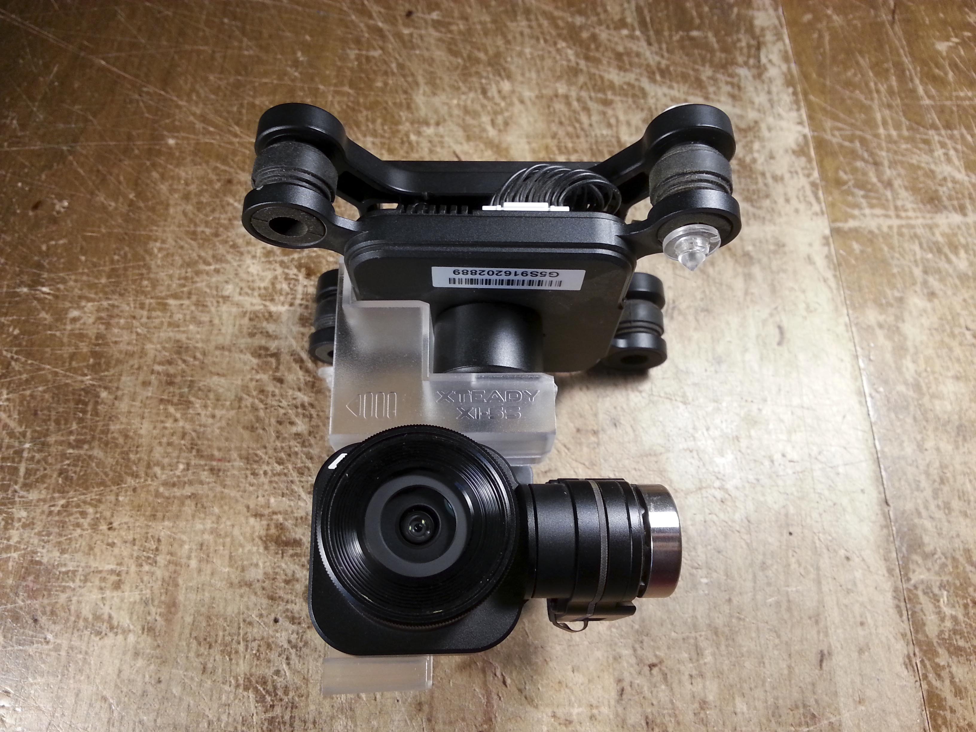
Let’s take a very brief look at the gimbal that comes with the X-Star. Unlike the Phantoms, Autel has made their gimbals easily removable with the press of a button. Large gold plated contacts and pads interface the gimbal to the aircraft:

I’m actually holding the gimbal the wrong way around in the image above. The button on the left side of the gimbal is supposed to engage the peg on the right side of the aircraft’s mount. The mounting mechanism feels a bit cheap and plasticy but I don’t see it popping off on its own.
Taking a closer look at the connector on the aircraft we can see that three pairs of pads are bridged on the PCB. The center two pads in both rows as well as the two pads in the upper right are bridged. These are most likely the power and ground busses. This leaves 6 lines for communication. I did not have the time to probe them, but I’d expect to find a USB interface between the camera and video transmitter as well as some sort of communications bus like CAN bus between the gimbal and flight controller.
I did not get a chance to take a look inside the base of the camera. The base is nicely machined from aluminum and has a small fan on top. The fan seems to be common on these 4k flying cameras. Interestingly the fan speeds up when making the gimbal compensate for fast movement (rotating the aircraft in my hands) and slows down then the gimbal is idle.

Looking down the side of the gimbal we see a single, intricate flat-flex cable snaking its way down to the camera head. The cable taps off at the roll and pitch gimbal control boards. The control boards are sandwiched between the gimbal frame and their machined aluminum covers.

Popping the cover off the back of the roll-axis reveals the roll motor driver PCB. The processor is a Microchip DSPIC33EP128MC504 16-bit “Digital Signal Controller.” This processor is designed for motor control, containing the 6 PWM channels needed to control the brushless roll-axis motor.
The potentiometer, which indexes to the flattened roll-axis shaft, provides position feedback to the controller. To the left of the pot is a SOT23 package marked “AE9A.” This is a LMV611 op amp and is most likely being used to scale the potentiometer output. The pot’s output will not go rail to rail because it’s rotation is limited to ~±45°) so to utilize the full resolution of the processor’s ADC the signal is amplified.

The motor is driven by three Alpha & Omega AON7804 dual N-channel MOSFETs. Each package is wired in a half H-bridge configuration and drives one phase of the brushless motor.
There are three 10-pin packages marked “ADEF 591” for which I could not find datasheets. I’m willing to bet, however, that these are gate drivers for the AON7804 MOSFETs. Like we saw with the brushless motor drivers on the main board, these gate drivers are controlled by the processor and provide sufficient voltage and current to drive the gates of the MOSFETs.
I was also unable to identify the tall package on the left side of the board. It is marked “MPFA 3620 641 M.” The 8-pin SOT just to its right marked “AEKF” is a Maxim Integrated MAX3051 CAN transceiver. The SOT-23 just below it is a Micrel MIC5219 3.3V 500mA LDO voltage regulator.
I would have liked to see some conformal coating on this PCB since it sits so low to the ground. The exposed edges of the board could easily wick water from wet grass.
When looking at my photos of this PCB I thought its layout and components looked familiar. Here’s the roll-axis PCB from a DJI Phantom 3 Standard:

Remarkably similar! Same uC, gate drivers and MOSFETs, similar potentiometer. DJI has some conformal coating over the FETs but I’d like to see some near the pot terminals, crystal and and uC.
Let’s take a quick look at the back of the camera itself:

On the back of the camera’s PCB we see yet another STM32F427II, this time using a 12MHz oscillator. The flat flex that snakes its way down from the base of the gimbal ends in a ZIF connector on this board. I did not remove this board from the shell because it appeared to have some sort of adjustment (by way of the two flat-head screws in the top left and bottom right corners) and I didn’t want to mess with it. There is also some adhesive along the perimeter of the PCB. The shell of the camera is made of machined aluminum.
There are four DFN packages on this board, three in a row near the top/center of the board and one to the right of the processor. Three of them are marked “CB6” and one marked “DAB.” As far as I can tell these are all Richtek RT8010/A DC/DC converters. These are probably being used to provide various voltages required by the sensor.
The markings on the QFN package at the top of the PCB are obscured by the light, but based on the small inductor and capacitors right next to it I’d venture to guess it’s another DC/DC converter.
The QFN package on the right side of the PCB is marked “M180B 15321 070AG” and doesn’t yield a datasheet. Right next to it is a 33Ω power resistor with a fat trace running to a transistor right above it. Not sure what’s going on there. In the bottom left are also two ICs that yield no datasheets.
Battery Charger

I wasn’t able to find an easy way to pop the cap off the battery, so I decided to take a look at this tumor on the battery charger lead. The plug pack was just a regular switch-mode power brick. Nothing too interesting there.

The battery end of the charger is this rather large black box with a fan in it. It has a hard rubber cap that covers the terminals. In addition to the two large charging terminals, there is a small 12 pin header molded into the connector. What could possibly be in this box that requires a fan and 12 additional pins?

To my surprise, it appears that Autel do all their cell balancing in this connector. The MOSFET which controls the battery’s charging is also housed in this unit. The fan is there to dissipate the energy burned off by the resistors. It’s operation is temperature controlled, only kicking in when the unit gets warm. The fan is fairly loud and only cycles between fully on and off.

We can see four sets of three 30Ω power resistors in parallel, giving us 10Ω per set. The battery is a 4-cell (14.8V) pack so each cell has its own set of balancing resistors. Each set is wired to the 12-pin connector and is switched via SOT-23 MOSFETs on the board. The FETs are marked “x72V” which yields no datasheet.
Another flavor of transistor on this board is marked “A8A.” These are ON Semiconductor MMUN2211L NPN transistors with built in biasing resistors. The fan is controlled by one of these.

An Alpha & Omega AO4407A P-channel MOSFET controls the charging in conjunction with the battery’s built in current sensing. It’s gate is driven by a MMUN2211L transistor.
On the back side of the board is a heatsink and a handful of components.

On the left is a 7805 5V linear regulator in a DPAK package. In the upper right are four transient voltage suppressors. These are probably in place to prevent static discharge from damaging the battery’s IO. Just below them are two footprints where diodes have been populated with 0Ω resistors. They must have been deemed unnecessary.
Faintly imprinted on the battery connector is the Molex logo. This is certainly a custom connector.
Remote Controller

I did not have the chance to disassemble the controller and further than the front plate. The controller looks well built and surely has some interesting stuff going on beneath the surface.
The right antenna sleeve contains one 900MHz antenna while the left antenna contains one 900MHz antenna as well as the 5.8GHz antenna. The 900MHz radio module is located under the LCD, while the 5.8GHz radio is buried inside the radio.
S.A. Muhammad,
Kudos to you on the very through tear down of the X-Star. I am starting an effort to reverse engineer the various systems of the X-Star, given that it is essentially dead as a product for Autel at this point. If you would like to stop by, the thread is here right now:
https://autelxpilots.com/threads/proposal-for-reverse-engineering-forum.1596/
If enough people are interested in this work, I will ask the admin for a topic category to be created. I found your observations on the gimbal interface of particular interest.
Hi John, Thank you for reading!
I think reverse engineering the X-Star is a great effort, as it seems to be a fairly capable platform. I will definitely be keeping an eye on the forum. The fact that it’s running PX4 is exciting.
I’ve also had a lot of interest in the gimbal and its interface. Unfortunately, I did not have an oscilloscope at the time to poke around the gimbal connector for signals. I do have a scope now, but having graduated from university I no longer have access to the X-Star 🙁
Best of luck!
Eu sou do Brasil e eu tenho esse drone x star Premium e tou com problema de comunicação de vide com a câmera do drone, a imagem da câmera aparece mas quando o drone sai 1m do chão ele pede o sinal da câmera. Tu tem alguma ideia o que seja?
Hiya. Have you made any progress on the rev eng? I emailed Autel and their response made it sound like I was asking them to send missle tracking parts to China. Thanks
Hey there,
I actually haven’t had access to an X-Star since the teardown, so no progress on my end. I don’t plan on buying one or anything.
Hey bud. Thanks for taking a minute to reply.
After I opened it up, the mobo was toast. Many shorted micro components. Two of the motors feel a little sticky. I may try to oil them and test.
I think I can stuff a Naza or pixhack into it, and there’s a bit of room in each arm for a normal esc.
I have a variety of miniature RC stuff: rx, vtx, but it would’ve been nice to get the gimbal functioning.
Have a nice day wherever you are.
Mike
Hello John. Any progress on reverse engineering a reverse engineered object…lol
Anyway, his view of the roll motor drivers , and subsequent explanation of only one phase of the motor being driven….with three chips being present, leads me to believe each chip drives one each of the 3 motors.
Eu sou do Brasil e eu tenho esse drone x star Premium e tou com problema de comunicação de vide com a câmera do drone, a imagem da câmera aparece mas quando o drone sai 1m do chão ele pede o sinal da câmera. Tu tem alguma ideia o que seja?
Os problemas da câmera não são fáceis de diagnosticar. Especialmente em dispositivos que não são mais suportados pelo fabricante. Normalmente, eu aconselharia você a comprar outra câmera que você sabe que funciona e experimentá-la. Se o problema ainda estiver lá, você pelo menos sabe que não é um problema com a câmera. Como você provavelmente não tem outra câmera, meu conselho é comprar algum limpador de contato elétrico, e poupar na interface do drone e da câmera. Observe que o álcool não substitui o limpador de contato.
I know it’s a few years later but I have an X-Star Premium with a new battery if you are interested. The new battery started to fail after a month as well as issues transmitting a constant video stream. I fly often and need something I can depend on. I would rather this go to a good cause. Just let me know.
Cheers.
Eu queria saber a referência do cabo flat da câmera e gimbal do x star é que o meu quebrou.
Hi Josael,
Unfortunately I do not know the part number of the flex cable.
Hi.
I am really impressed with your teardown….which I initially thought was just going to be a. Few plastic parts piped off to get sand out!!
I am particularly interested, as I have found others to be, in the pin out of the gimbal. I found a crashed xstar in the river, and have no real desire to fly it, especially if the airframe components are fluxxed up. The gimbal however would be cool to get functioning as an item I could hang from one of my alien 560s.
Thanks for your time bro, Mike
Hey Mike!
Sorry for the massive delay in replying. I didn’t have comment notifications on for some reason.
Unfortunately I don’t have access to the X-Star anymore. I’ve actually moved away since then! If only I could find one in a river around here 🙂
Hello Muhammad Al-Rawi,
Can you find the datasheets of ADEF591?
I have one Gimbal Ronin and it work with ADEG672 and the AON7804.
The motor shake very and don´t stabilize.
If you find this document, can you share it with me?
Thanks,
Max
Here….
https://www.monolithicpower.com/pub/media/document/MP1907_r1.2.pdf
Oh wow.. this is almost exact copy of Phantom 3.
I wonder if the firmware is strangely similar as well.
I believe I read a post a while back where someone saw some PX4 related logs/debug while poking around the X-Star.
Thanks for the IC identification! I’ll update the post.
btw, AEKF = Maxim MAX3051EKA-T CAN Transceiver, Dji uses it as well.
Could you explain what my problem is if mine won’t hover but does everything else
Have you tried contacting autel support? There’s a FB page for the eco and xstar.
Since a massive problem with these drones is failing batteries, and Autel has discontinued supporting them, do you think it would be possible to mod the wiring in the case for a regular 3S RC lipo battery?
Hey man. I cant speak much for the Autel products, but on the 3dr Solo the support group has several excellent mods for replacement lipo packs. They all involve using either the stock device thats attached to the factory lipo, or a new mod version…that are designed to correctly charge the battery. If the Autel lipo has one built in…make sure you carefully remove it and study it, either to connect to your replacement pack, or better yet to build a duplicate from. On the Solo, guys have gone from 15 minute flights with stock packs even years ago, to close to 20…in addition…people are using sanyo 18650 cells to make packs, and getting about 22-23 minutes due to lighter weight. The Solo thing is called a BMS…battery monitor system.
only a few survived.
Hey man do you think you could help me identify an ic on the smb in the battery with a clean picture? I need to replace it
Bms
Hey Chris,
I never took the pack apart so I don’t know what BMS IC is used inside. If you have a good photo of the markings there’s a chance we can ID it.
Keep in mind most BMS ICs get programmed with pack specific parameters, so replacing it may not necessarily bring it back to life.
I do! How would I get the photo to you I dont see an upload on here
Hey. Do u know where the single black wire attached to on top of battery coming from the board?
I do have really close photos I think its the voltage regulator but would like to confirm that chip
Hey. Do u know where the single black wire attached to on top of battery coming from the board?
I think you might be referring to the thermistor. If so, it is a temperature sensor. Only attached at one end.
Hello,
Excellent breakdown, so sad that autel has given up on such an expensive piece of equipment.
I was curious if anyone’s taken a X Star apart and reused motors or anything on a 3d printed drone setup? Sadly the X Star I have is just taking up too much space and collecting dust.
Thank you
A few decades ago when the TBS discovery came out, people were taking the guts from Phantoms and mounting them up as an easy peasy “custom quad…being lighter they were able to get 45-60mph out of them…